Bias Point Analysis
· To open a new schematic window
Start Schematics.
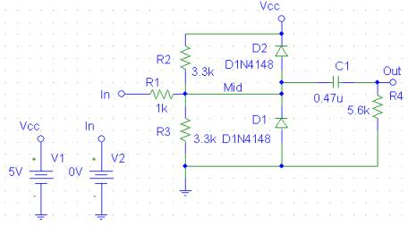
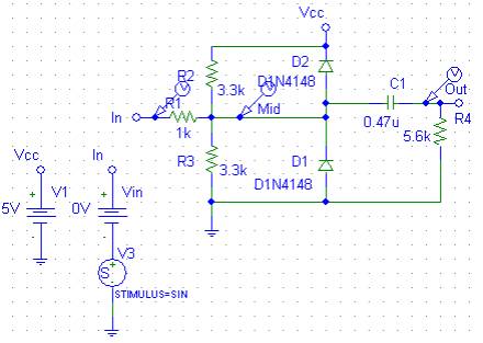
· To place the voltage sources
From the Draw menu, select Get New Part to display the Part Browser dialog box.
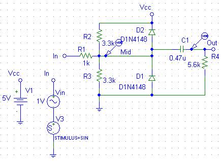
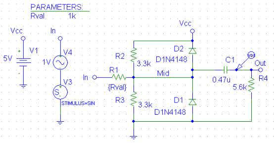
In the Part Name text box, type VDC, C, R, D1N4148, gnd, bubble. Click Place & Close.
Move the pointer to the correct position on the schematic.
· Assign names (labels) to the nets and bubbles
· Assign names to devices
· Change the attribute values of devices
· Save your schematic
· Simulate the circuit using Pspice
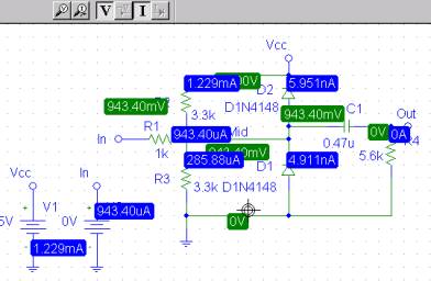
![]()
On the Simulation toolbar, click the Enable Bias Current and Bias Voltage Display button.
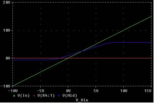
DC Sweep Analysis
Setting Up and Running a DC Sweep Analysis
To set up and run a DC sweep analysis
· In the Analysis Setup dialog box, click the DC Sweep button.
· Set up the DC Sweep dialog box.
· From the Analysis menu, select Simulate to run the analysis as specified.

· Click to place a marker on net.
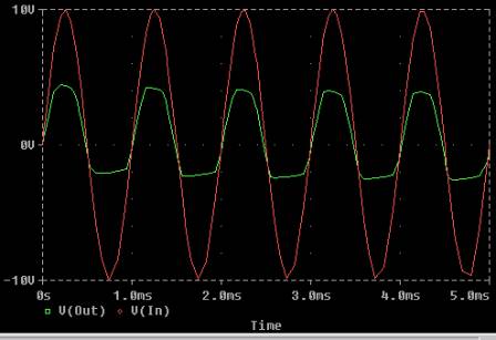
Transient Analysis
· Place a VSTIM symbol.
· Double-click the VSTIM symbol.
· In the Set Attribute Value dialog box, type SINE, then click OK.
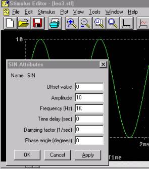
· The New Stimulus dialog box and the Stimulus Editor appear.
· In the Stimulus Editor, click SIN, then click OK.
· In the SIN Attributes dialog box, set the first three parameters as follows:
Offset Voltage = 0
Amplitude = 10
Frequency = 1kHz
· Click OK.
· From the File menu, select Save to save the stimulus information.
· From the File menu, select Exit.
· In Schematics, from the Analysis menu, select Setup.
· click Transient to display the Transient Analysis dialog box.
· Set up the Transient dialog box.
· Click OK.
· Clear the DC Sweep check box to disable the DC sweep.
· From the Analysis menu, select Simulate.
· In Probe, from the Trace menu, select Add.
· Select V(In) and V(Out) by clicking them in the trace list.
· Click OK to display the traces.
AC Sweep Analysis
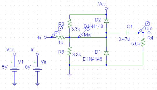
· Click the DC voltage source to select it.
· From the Edit menu, select Replace. In the Replace Part dialog box, type VAC.
· Double-click the displayed (AC) value of the new Vin.
· In the Set Attribute Value dialog box, set the value to 1V.
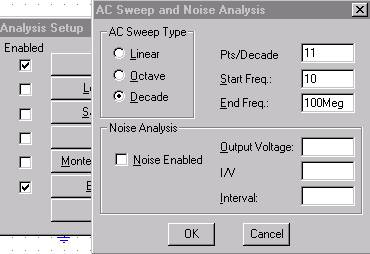
To set up the AC sweep and start simulation
· From the Analysis menu, select Setup.
· In the Analysis Setup dialog box, click AC Sweep.
· From the Markers menu, select Mark Advanced.
· Double-click Vdb.
· Place one Vdb marker on the output net, and place another on the Mid net.
· From the Analysis menu, select Simulate to start the simulation.
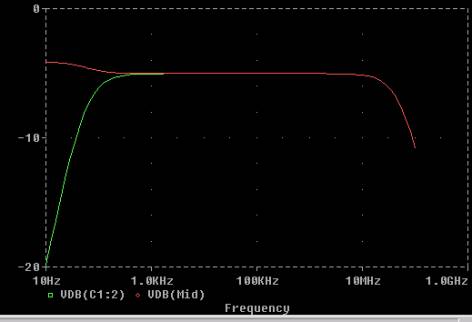
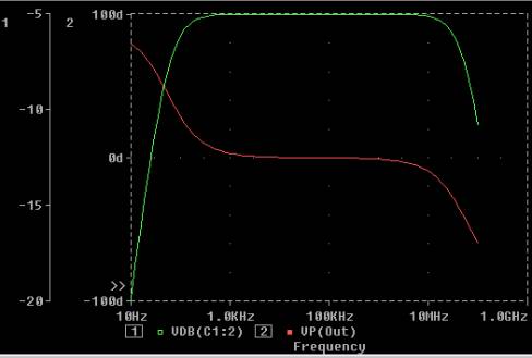
To display a Bode plot of the output voltage, including phase
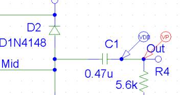
· In Schematics, from the Markers menu, select Mark Advanced.
· Place a Vphase marker on the output next to the Vdb marker.
· Delete the Vdb marker on Mid.
· Click the trace name VP(Out) to select it.
· From the Edit menu, select Cut.
· From the Plot menu, select Add Y Axis.
· From the Edit menu, select Paste. The Bode plot appears.
Parametric Analysis
· Double-click the value label for R1.
· In the Set Attribute Value dialog box, type {Rval}.
· Click OK.
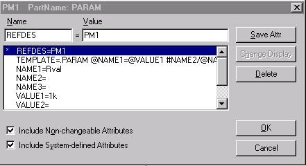
· From the Draw menu, select Get New Part.
· In the Part Name text box, type PARAM, then click Place & Close.
· Place one PARAM symbol on any open space on the schematic.
· Double-click the PARAM symbol to display the attributes list.
· Double-click NAME1 and type Rval (no curly braces) in the Value text box.
· Click Save Attr to accept the change.
· Double-click VALUE1, type 1k, then click Save Attr.
· Click OK.
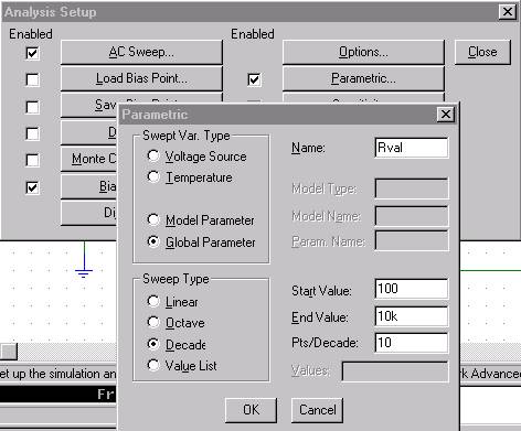
· In the Analysis Setup dialog box, click Parametric.
· Set up the Parametric dialog box.
· Click OK.
· Delete the VP marker.
· Clear the Transient check box, and click Close to exit the Analysis Setup dialog box.
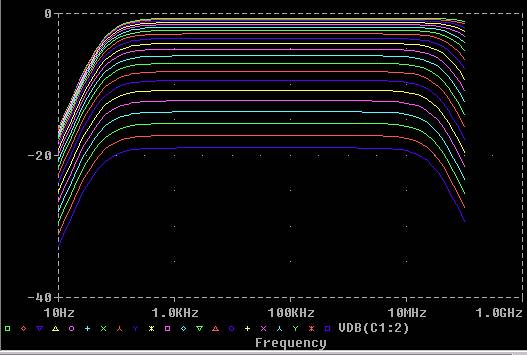
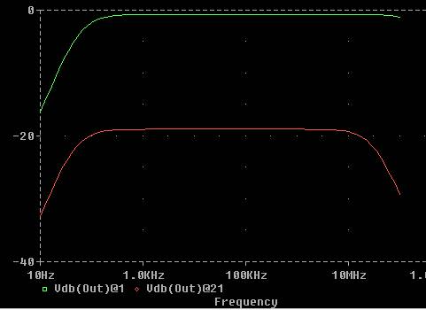
To compare the last run to the first run
· From the Trace menu, select Add.
· In the Trace Expression text box, type the following:
· Vdb(Out)@1 Vdb(Out)@21
· Click OK.