|
7. Adding a Current Source :
|

|
IAC - Simple AC current source
|
|

|
IDC - Simple DC current source
|
|

|
IPULSE - Pulse current source
|
|

|
IPWL - Piecewise linear current source
|
|
|
|
8. Adding a Voltage Source :
|

|
VAC - AC Voltage Source
|
|

|
VDC - DC Voltage Source
|
|

|
VPULSE - Voltage Pulse Source
|
|

|
VSRC - AC or DC Voltage Source
|
|

|
VSTIM - Voltage source for StmEd
|
|
|
9. Changing the settings for current / voltage sources :
TD - Time delay
TR - Rise Time
TF - Fall Time
PER - Period
PW - Pulse width
VOFF - Offset voltage
FREQ - Frequency
VAMP- Amplitude
|
|
10. Adding Connection bubbles :
· Adding connection bubbles
Bubbles are components used to connect one part to another without using wire connection.
|

|
Select Draw/Get new part [Ctrl+G] or click on the get new part icon to get new part.
In the Part Name text box, type bubble.
Place the connection bubble in the circuit.
|
|
|
11. Adding Probes :
· Adding a marker to a node
Voltage and current markers are used to probe the voltage or current.
After simulation, PSPICE automatically plot the results.
|

|
Voltage marker
|
Select Markers/Mark Voltage/Level [Ctrl+M] or click voltage marker icon to place the voltage marker.
|
|

|
Current marker
|
Select Markers/Mark Current into Pin or click current marker to place the current marker.
|
|
 
|
Voltage Differential marker
|
Select Markers/Mark Differential Voltage. Place the two marker + and - between the circuit.
|
|
|
Advanced marker
|
Select Markers/Advanced
Place the marker on the circuit.
|
|
|
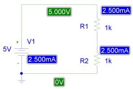
12. Enable Bias voltage display and Bias current display Icon
|

|
|
After simulation, the DC values of voltage and current can be displayed using these functions.
|
|
|
|
|
|
|