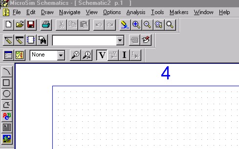
2. To create/open a schematics file :Click on the Schematics icon on Design Manager to open MicroSim Schematics. Select File/New or click on the new file icon to create new file. Select File/Open or click on the open file icon to open existing file.
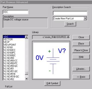
Select Draw/Get new part [Ctrl+G] or click on the get new part icon Part Browers Advanced windows is shown below.
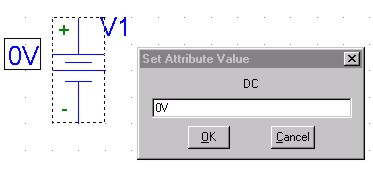
In the Part Name text box, type name of the component e.g. VDC. Click Place & Close icon. Move the component to the correct position on the schematic. Right-click to cancel placement. 3. Changing the value of a component:Double-click on the attribute value to change the values of a component e.g. 0V. In the Set Attribute Value dialog box, type the correct value. Then Click OK.
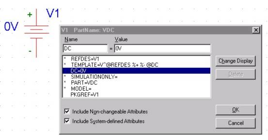
Or Double-click on the component to change the other values of a component.
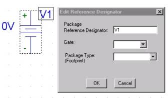
4. Changing the reference number of a component:Double-click on the current reference number e.g. V1 to change the reference number of a component.
5. Edit the component :· Moving a component: Click on the component once to select it. Drag the component to a new location. · Rotating a component: Click on the component once to select it. Select Edit/Rolate [Ctrl+R] to rotate the component in 45 degree. · Flipping a component: Click on the component once to select it. Select Edit/Flip [Ctrl+F] to flip the component. · Deleting a component: Click on the component once to select it. Select Edit/Delete [DELETE] to delete the component. 6. Wiring :Select Draw/Wire [Ctrl+W] or click on the draw wire icon Press Right-Click mouse or [ESC] to finish wiring. · Labeling a wire Double-click on the wire to select it. In the Set Attribute Value window type the label of the wire. |
|||
 to get new part.