Design Entry1. To open a Design Manager : |
||||||||||
To open the Evaluation Version
|
||||||||||
|
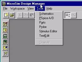
The Design Manager Windows is shown below.
|
|
|||||||||
|
Schematics is a design entry program you need to prepare your circuit for simulation. Placing and connecting part symbols, Defining component values and other attributes, Defining input waveforms, Enabling one or more analyses, and Marking the points in the circuit where you want to see results. Schematics is also the control point for running other programs used in the simulation design flow.
The Parts utility is a model extractor that generates model definitions for PSpice to use during simulation. All the Parts utility needs is information about the device found in standard data sheets. As you enter the data sheet information, the Parts utility displays device characteristic curves so you can verify the model-based behavior of the device. When you are finished, the Parts utility automatically creates a symbol for the model so you can use the modeled part in your schematic immediately.
Probe is a graphical results analyzer. When PSpice completes the simulation, Probe plots the waveform results so you can visualize the circuits behavior and determine the validity of your design.
The Stimulus Editor is a graphical input waveform editor that lets you define the shape of time-based signals used to test your circuits response during simulation. Using the Stimulus Editor, you can define analog stimuli with sine wave, pulse, piecewise linear, exponential pulse, and single-frequency FM shapes. The Stimulus Editor lets you draw an analog piecewise linear stimulus by clicking at the points along the timeline that correspond to the input values you want at transitions. |
||||||||||