5. Using the Selection Filter :
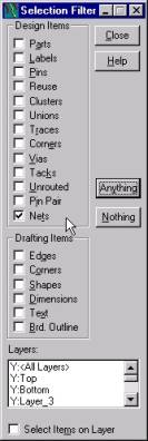
To focus your selections on specific objects, PowerPCB has a Selection Filter. The Selection Filter allows you to specify which design objects can be selected.
· To access and review the Selection Filter:
Select Edit/Filter to open the Selection Filter dialog box.
Objects are organized into three categories—Design Items, Drafting Items, and Layers.
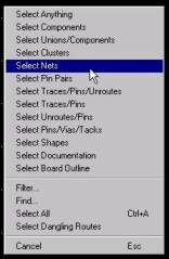
· Selection Filter Shortcuts :
Click the right mouse button while no object is selected, a pop-up menu containing a list of Selection Filter shortcuts appears.
Select one of these shortcuts updates the Selection Filter to include only the items in the shortcut description.
Select Nets shortcut and note how the selection filter is updated to allow selection of nets only.
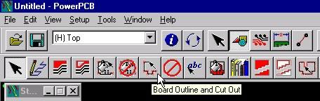
6. Creating a Board Outline :
It defines the board boundary.
|
|
|
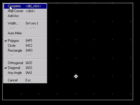
After draw the board outline to define the board boundary.
Click the right mouse button to open the pop-up menu, then choose Complete,
or Double-click the left mouse button, to close and complete the polygon.
|
|
Then, Click the Board icon [Ctrl-B] from the toolbar to fit the board outline to the screen. |
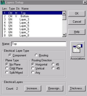
7. Setting the Layer of the PCB :
To assign the number of layers, the nets associated with embedded plane layers, layer stackup, and layer thickness.
Select Setup/Layer Definition. The Layers Setup dialog box appears.
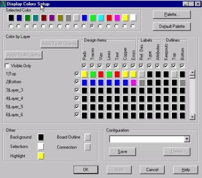
8. Setting Layer Colors :
Select Setup/Display Colors. The Display Colors Setup dialog box appears.
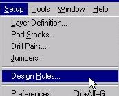
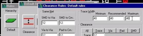
9. Setting Design Rules and Trace width :
To assign and edit rules, or width, spacing and general routing.
Select Setup/Design, Click Default icon and Clearance icon to set Trace Width.
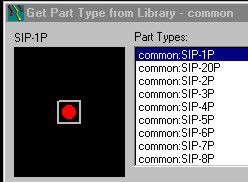
10. Setting Pad Stack width :
Example
From Get Part, Select SIP-1P.

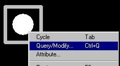
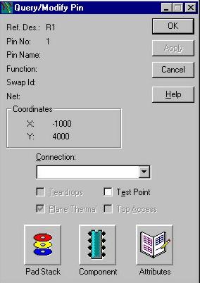
Select the Pads of components. and click right mouse to select Query/Modify to modify Pad Stack.
Click the Pad Stack icon.
Input the Diameter of Pad. Click OK.
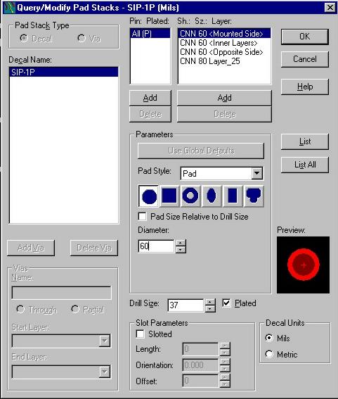
Click All or Selected components.
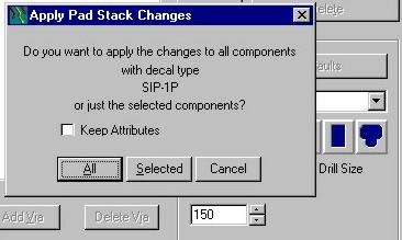
After increase the diameter to 150. =)